RealTime Electronic Conductor Baton
The Project
The goal of this project is to engineer the foundation for a robotic band member that takes in a user-defined song, observes a conductor’s tempo changes in real time, and plays the notes at the defined beats per minute (BPM) on both the hardware and on the GUI. The instrument that was chosen to emulate was the bass guitar.
My Role
I was primarily responsible for developing the baton, instrumenting the accelerometer in the baton, and utilizing the real-time mechanics of the ESP32. I instrumented the IMU to an ESP32 using I2C communication protocol, then used UART to send accelerometer data between two ESP32s, as the second “listening ESP32”
The accelerometer
Reading data after instrumenting the IMU was relatively straightforward. The raw data needed to be divided by a constant to provide values which were adjusted to Earth Gravity. I also needed to make sure that I had a constant time tick such that I would be able to detect sudden changes in acceleration in the correct direction, for instance if the conductor was counting in 4-4 time, and backcheck against the time to make sure the swing was a true swing.
while True:
    # Read data from MPU6050
    #Values adjuected for Earth Gravity
    X = (raw_data[0] << 8 | raw_data[1]) / 16384.0
    Y = (raw_data[2] << 8 | raw_data[3]) / 16384.0
    Z = (raw_data[4] << 8 | raw_data[5]) / 16384.0
    g=abs(Z)
    #Calc change in accel
    #3.6 threshold sensitivity value
    if ((g-prev_g)>THRESHOLD and prev_g<g):
        #Calc time in milliseconds
        stime=interruptcount*10
        #Check to see if the time is within bounds, and the range swing is not too great
        if (stime>100 and stime<9999 and abs(stime-prev_stime)<2000):
            dtime=stime
            prev_stime=stime
        #reset counters
        stime=0
        interruptcount=0
    #Store previous gravity data
    prev_g=g
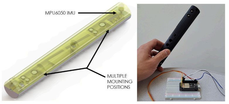
The Baton
After interfacing with the accelerometer via I2C and initializing the firmware as required, I wrote an interrupt service routine (ISR) which polls the accelerometer constantly at a fixed rate. This rate was eventually chosen to be 10ms, which was found to be fast enough for the microprocessor, and ensured that the computation for time would be simple. An exmaple of the ISR:
def accelInterrupt(timer):
global raw_data
global interruptcount
interruptcount=interruptcount+1
#Asking for data, reading from MPU
i2c.writeto(MPU_addr, bytes([0x3B]))
raw_data = i2c.readfrom(MPU_addr, 6)
Going line by the line, the first line defines some global variables which are shared between the ISR and the main loop of the code. This includes the “raw_data” variable which stores the raw
data retrieved from the accelerometer and “interruptcount” which counts the number of times this particular ISR is triggered.
Next, the “interruptcount” variable is incremented by one to indicate the ISR has been triggered. The I2C is then utilized to write bytes to the accelerometer. This triggers the accelerometer to
report the data back to the ESP32, which it reads using the “i2c.readfrom” command and stores into the “raw_data” variable.
This ISR allows us to use itself as a timer, as the main loop constantly checks to see if a downward swing inflection was reached. The team is then able to use the interruptcount variable
to tell how much time elapsed knowing how often the ISR is triggered.
Sending Data to the Second ESP32
On the same host ESP32, a second interrupt is running to handle the rate at which data is being sent to the client ESP32. The data is sent via the UART lines of the two ESP32 devices. This was done because the client ESP32, which interfaced with LabVIEW and the hardware, was running in a blocking/listening format. Here, the ISR is far less complex:
def uartInterrupt(timer):
    global dtime
    uart.write(str(dtime))
All this ISR does is run a simple “uart.write” function: it takes the “dtime” variable, casts it as a string byte, and sends it to the client ESP32. However, what is important about this ISR is that it runs in such a way that ensures no ISR collisions can occur within the code.
Collision Conditions
Because there are two ISRs which run on the host ESP32, it is important to ensure that the “accelInterrupt” is not colliding with “uartInterrupt.” I achieved this by utilizing prime numbers. Because a prime number can only have two multiples, 1 and itself, I can be confident that no matter how long the ESP32 runs the programs and interrupts, they will never collide with each other. I ultimatel chose the “uartInterrupt” to run every 2111 milliseconds for two reasons. Firstly, this interrupt speed was found to be the fastest prime number interrupt that I could utilize without sacrificing and interrupting the client ESP32’s hardware. After extensive testing with prime numbers closer to 1000 milliseconds, it was found that these values were too fast and interrupted the note commands received from LabVIEW, causing the hardware to lag and not perform properly. Moreover, I found that 2111 milliseconds was a time which would not overtly affect conducting, as most songs conducted in the 4/4 time signature would have a measure elapsing often double 2111 milliseconds.
The Listening ESP32, Decoding Incoming Data
The client ESP32 reads data at a constant rate, the same rate at which the data is being sent. This synchronization allows the UART buffer to be dequeued at a constant rate, which will avoid the client reading older data, and prevent UART buffer overflow. As seen in the ISR:
def uartInterrupt(timer):
    global converted
    if uart.any():
    data=uart.read(5)
    converted = int(data.decode('utf-8', 10))
    print(converted)
it checks the UART for any data stored in the UART buffer. From there, it will convert the read data from the byte array into a base-10 integer, utilizing the utf-8 encoding. Finally, it prints the converted data for the user to verify its correctness, but is taken out of the ISR in normal operation to reduce time spent within the ISR.